OCPP Service | ZJ Beny Charger - Network Configuration Guide
- Step 1 : Enter AP Configuration Mode
- Step 2 : Enter the configuration interface
- Step 3 : Make network configuration
- Step 4 : Make OCPP Central System Configuration
- Step 5 : Make DLB Configuration
- Step 6 : Make RFID Configuration
- Step 7 : Do other configuration
- Step 8 : Make Password Configuration
- Step 9 : WPS Connection Method
- Step 10 : Exit Web Configuration Mode
Step 1 : Enter AP Configuration Mode
The network configuration of the EV charger needs to be done when the connector is disconnected from the
EV. If the connector is already plugged into the car's charging socket, please unplug it first.
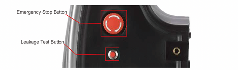
The method for the charger to enter AP configuration mode:
- Disconnect the charger.
-
Press the emergency stop button.
-
Press and hold the leakage test button and do not release it.
-
Power on the charger.
-
Release the leakage test button and emergency stop button after the charger beeps.
When the yellow light in the LED flashes, the charger has successfully entered AP configuration mode.
Step 2 : Enter the configuration interface
- A Wi-Fi routing signal via a computer or mobile phone connected to the charger, where the Wi-Fi name starts with EVSE plus a combination of numbers. The default Wi-Fi password is "12345678".

- Use your browser to access 192.168.1.1, just like configuring your router. Google Chrome is recommended for better compatibility.

Accessing the charger via a browser will take you to the configuration interface where you can see a number of configurations. These are: Network Configuration, Central System Configuration, DLB Configuration, RFID Configuration, Other Configuration, Password Configuration and Exit Web Configuration mode.

Details of each configuration item in the configuration interface are shown in Table 2.1:
Table 2.1 Details of each configuration item in the configuration interface

Step 3 : Make network configuration
- Click on the Network Configuration button to enter the network settings interface, where you can see a number of NetWork setting options.

Details of the network settings items are shown in Table 3.1:
Table 3.1 Network setup item details

If you want the charger terminal to connect to Wi-Fi by entering the wireless network name and wireless network password, you will need to select the Wi-Fi Custom mode network settings and configure the network according to the following steps:
- Click to select "Wi-Fi Custom".

- Scroll down the interface to find WIFI Config and enter the corresponding Wi-Fi name (Wi-Fi SSID) and Wi-Fi password.

The descriptions of the Wi-Fi configuration items are shown in Table 3.2:
Table 3.2 Wi-Fi configuration item descriptions

If you wish to configure the charger for network via a 4G connection, you will need to confirm that your charger supports 4G networks, that the SIM card is inserted into the charger and that the SIM card is not PIN encrypted, and then configure the network according to the following steps:
- Click to select "4G”.

- Scroll down the interface and find LTE Config and fill in the LTE configuration fields.

The descriptions of the LTE configuration items are shown in Table 3.3:
Table 3.3 Description of LTE configuration items

If you want the charger terminals to be networked via Ethernet, you will need to connect a network cable to the Ethernet RJ45 port of the EV charger and then configure the network according to the following steps:
- Click to select "Ethernet".

By default, the IP Config of an EV charger is a Dynamic IP (DHCP) configuration, i.e. the server automatically assigns an IP address to the internal network or to the ISP. If you need to set a fixed IP address to access the Internet, you need to select Static IP Config and fill in the appropriate Static IP, Gateway and Netmask, otherwise you can leave it as default.

- Click the SAVE button to exit the Network Configuration interface and return to the Configuration Page.
Step 4 : Make OCPP Central System Configuration
Note: If you selected a non-offline network setting (Wi-Fi WPS, Wi-Fi Custom, 4G, Ethernet) when you made your network settings, you will need to make OCPP central system configuration, otherwise please kindly ignore this step.
- Click on the "OCPP Central System Configuration" button to configure the OCPP central system.
-
Make security settings. You can choose whether or not to enable SSL encryption depending on the server.

The setting items for Security are described in Table 4.1:
Table 4.1 Description of the setting items of the security settings

- Set up the Server.
Please fill in the Central System Hostname, Central System Port, Charge Point Identity and Charge Point Path as appropriate for your server.

The settings of the Server are described in Table 4.2:
Table 4.2 Description of the server's setup items

- Make HTTP Basic Authentication settings.
Please choose whether to enable HTTP basic authentication according to the needs of the OCPP cloud platform service. If you choose to enable, you need to fill in the corresponding Authorization Username and Authorization Password, otherwise you do not need to fill in.

The HTTP Basic Authentication settings are described in Table 4.3:
Table 4.3 Description of the setting items for HTTP Basic Authentication

- Make Custom Vendor Info settings.
This setting requires you to fill in the Charge Point Model and Charge Point Vendor. When you fill in, the functionality will achieve: The custom EV charger model and manufacturer name will be submitted to the server, when the EV charger is logged into the server. Please ignore this step if you do not require this functionality

The settings for Custom Vendor Info are described in Table 4.4:
Table 4.4 Description of setting items for customized supplier information

Click the SAVE button to exit the OCPP Central System Configuration interface, and return to the Configuration Page.
Step 5 : Make DLB Configuration
Note: EV chargers can be fitted with DLB boxes for dynamic load balancing or PV energy management functions. If the charger is fitted with a DLB, you will need to configure the DLB. Otherwise, please kindly ignore this step.
Note: The configuration items on this interface allow you to configure the DLB function of the EV charger. Please check the "DLB manual" for details of the DLB function.
- Click on the "DLB Configuration" button to configure the DLB.
-
Make general settings.
In the DLB general settings, you can choose whether to use the DLB function and set whether to enable the DLB extreme mode. When you activate the DLB extreme mode, the charger will stop charging according to certain conditions set by the DLB. Otherwise the charger will maintain a charging current of greater than or equal to 6A.
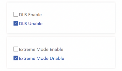
The setting items for the DLB General settings are described in Table 5.1:
Table 5.1 Description about the setting items of the DLB General Settings

- Make Normal DLB settings
In this configuration, you can set the overload current of the DLB. The normal DLB overload current setting range is 6-99A.

The setting items for the Normal DLB are described in Table 5.2:
Table 5.2: Description about the setting items of the Normal DLB

- Make Solar DLB setup.
In this configuration, you can set whether to enable the full speed charging mode at night and select the charging modes as required, including Only Solar Mode, Hybrid Mode, Full Speed Mode and “Use the Settings above the DLB box”. When selecting Hybrid Mode, you can set the maximum grid current allowed in Hybrid Mode.

The setup items for the Solar DLB are described in Table 5.3:
Table 5.3 Description of the setting items of the solar DLB

- Make DLB on cloud setup.
In this configuration, you can set the DLB Date Transfer Interval. If you need to enable it, it has a minimum setting of 10 seconds and stop the process when the setting is 0.
Note: DLB data is customised data outside of the OCPP protocol. Therefore it requires an OCPP server to support this customization, otherwise enabling reporting will not work.

The setup items for DLB on cloud are described in Table 5.4:
Table 5.4 Description of DLB Cloud setup items

- Click the SAVE button to exit the DLB Configuration interface and return to the Configuration Page.
Step 6 : Make RFID Configuration
Note: If you have selected the Plug and play mode when doing the network setup, RFID configuration is not required. Please ignore this step, otherwise please do the RFID configuration.
- Click on the "RFID Configuration" button to configure the RFID.
- Make the General setting. In this setting, you can set the RFID card to be used only when the charger is offline or at any time.

The descriptions of the RFID General Settings items are shown in Table 6.1:
Table 6.1 Description of the general setting items for RFID configuration

- Do the RFID Unique Config.
In this configuration, you can choose whether or not to enable the RFID Unique configuration. If so, you will need to fill in the corresponding RFID Unique ID.
Example: If your IC card number is "9E46BA0D", you need to configure Unique ID as "9E46BA0D".

The configuration items for RFID unique configuration are described in Table 6.2:
Table 6.2 Description of each configuration item for RFID unique configuration

- Make Reader mode configuration.
This configuration allows you to set the reader mode of the charger, including RFID UID mode, RFID Custom mode and RFID Manufacturer mode. If you select RFID Custom mode, you will need to enter the card number storage address and set the RFID Custom Password in the RFID Custom Block.

The configuration items for the reader mode configuration are described in Table 6.3:
Table 6.3 Description of configuration items for reader mode configuration

Click the SAVE button to exit the RFID Configuration interface and return to the Configuration Page.
Step 7 : Do other configuration
- Click on the "Other Configuration" button to enter the other configuration interface
-
Do parameter configuration.
-
In this configuration you can set The maximum current of the one connector, the Meter Value Sample lnterval and the ConnectionTime Out setting.
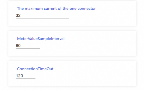
The configuration items for the parameter configuration are described in Table 7.1:
Table 7.1 Description of configuration items for parameter configuration

- Do the ground fault detection.
When the charger encounters a ground failure or poor grounding, which the function of the ground fault detection is to report a ground disconnection warning, which triggers ground protection. Thus, it prevents the charger from charging the vehicle.

The ground fault detection options are described in Table 7.2:
Table 7.2 Description of ground fault detection options

- Make the External Meter Enable setting. If this configuration is enabled, the charger will use the data from the external meter as its own metering data. Turn this on if an external meter is already installed.
Note: The brand and type of external meter used for the charger should be specified by the manufacturer, and it is recommended that the user only change this configuration on the first installation.

The external meter enablement options are described in Table 7.3:
Table 7.3 Description of external meter enablement options

- Make the Dry Contact Enable setting. If this configuration is enabled, the charger will determine if the charger is in a period where charging is allowed based on the status of the dry contacts.

The dry contact enablement options are described in Table 7.4:
Table 7.4 Description of dry contact enable options

- Make Authorization Cache setting. If this configuration is enabled, the card will have a cache record and the charger will still be able to be charged for a certain period of time when the server is unexpectedly offline.

The cache authorization options are described in Table 7.5:
Table 7.5 Description of cache licensing options

- Click the SAVE button to exit the Other Configuration interface and return to the Configuration Page.
Step 8 : Make Password Configuration
- Click on the "Password Configuration" button to enter the password configuration interface.
-
The password configuration interface allows you to change the charger Wi-Fi password. If you need to change the charger Wi-Fi password, you will need to enter the Wi-Fi password you are currently using in the old password entry field, and then enter the new password you wish to change and use in the new password entry field.

The settings for Change Password are described in Table 8.1:
Table 8.1 Description of setting items for password change

When you forget your password, you can restore it to its default value through the following ways: You can press and hold the reset button inside the EV charger for 20 seconds after pressing the emergency stop button.

- Click the SAVE button to exit the Password Configuration interface, and return to the Configuration Page.
Step 9 : WPS Connection Method

Step 10 : Exit Web Configuration Mode
- When the settings are complete, click on the "Exit Web Configuration Mode" button. The EV charger will automatically connect to the server according to the parameters set.
-
Network configuration is successful when you see the charger's first green light in a breathing light state. If the charger's first green light blinks slowly (on for 1 second, off for 1 second), then the configuration has failed. You should go back and reset the network settings.